
WHEELTOP EDS OX 2.0 — Installation, Pairing & Calibration Manual
← Back to User ManualsOn this page
This is a complete page-by-page reproduction of the official WHEELTOP EDS OX 2.0 User Manual V3.0.1 — every diagram and instruction from the printed PDF, rebuilt as a searchable web page. For the original file, use the PDF download in the sidebar.

WHEELTOP EDS OX 2.0 — Electronic Derailleur System
User Manual V3.0.1
Contact & App
Lanxi Wheel Top Cycle Industries Co., Ltd.
TEL: +86(579) 83881076 / 83888356
Download the WHEELTOP App
Search "WHEEL TOP" on Google Play or the App Store to download the app.
Important Notice
For safety, please read this user manual carefully before using the product and follow the instructions for proper use.
Safety Instructions
Before installation, you must read and understand the safety instructions included with the product. Improper installation of components is extremely dangerous and may cause severe or even fatal injuries. If you have any doubts about component installation, consult a professional bike mechanic.
Note
This manual serves as a complete system installation guide, covering the entire process from unboxing each component to starting your ride. Follow the sequence outlined in this manual to complete installation and setup step by step. Begin the next step only after completing the previous one. For product sales regions, refer to the official website for details. If sold in unlicensed areas, responsibility lies with the seller.
This equipment complies with Part 15 of the FCC Rules.
Operational Requirements: (1) This device must not cause harmful interference. (2) This device must accept any interference received, including interference that may result in undesirable operation. Any changes or modifications not expressly approved by the party responsible for compliance could void the user's authority to operate the equipment.
FCC Compliance: This device has been tested and found to comply with the limits for a Class B digital device under Part 15 of the FCC Rules. These limits are designed to provide reasonable protection against harmful interference in residential installations. The device generates, uses, and can radiate radio frequency energy. If not installed and used according to the instructions, it may cause harmful interference to radio communications. However, there is no guarantee that interference will not occur in specific installations. If harmful interference occurs, users can try the following remedies: adjust the direction of the receiving antenna; increase the distance between the device and the receiver; connect the equipment to a different circuit than the receiver; or consult the dealer or an experienced technician for help.
This device complies with FCC radiation exposure limits set for an uncontrolled environment. Maintain a minimum distance of 20cm between the radiator and your body during operation and installation.
Tools Needed
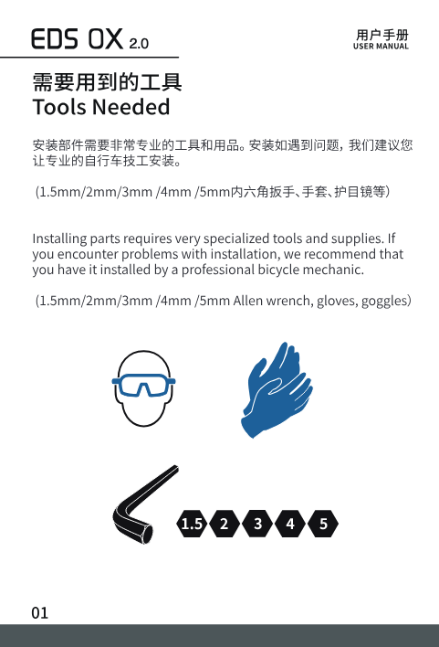
Installing parts requires very specialized tools and supplies. If you encounter problems with installation, we recommend having it installed by a professional bicycle mechanic.
- Safety goggles
- Gloves
- 1.5mm / 2mm / 3mm / 4mm / 5mm hex wrenches
Component Overview
Shifter
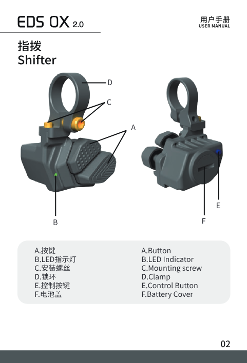
A. Button B. LED Indicator C. Mounting Screw D. Clamp E. Control Button F. Battery Cover
Rear Derailleur
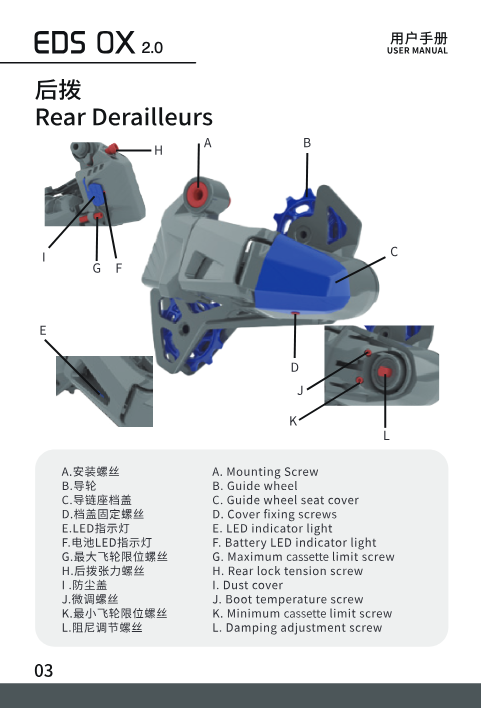
A. Mounting Screw B. Guide Wheel C. Guide Wheel Seat Cover D. Cover Fixing Screws E. LED Indicator Light F. Battery LED Indicator Light G. Maximum Cassette Limit Screw H. Rear Derailleur Tension Screw I. Dust Cover J. Fine-Adjustment Screw K. Minimum Cassette Limit Screw L. Damping Adjustment Screw
Labels H and J are corrected here — the original PDF's English column mistranslates them as "Rear lock tension screw" and "Boot temperature screw."
Charging
Charging the Rear Derailleur
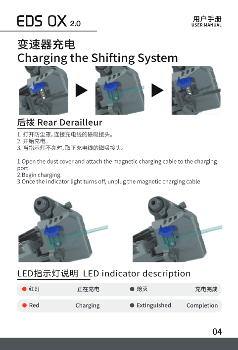
- Open the dust cover and attach the magnetic charging cable to the charging port.
- Begin charging.
- Once the indicator light turns off, unplug the magnetic charging cable.
LED indicator: Red = Charging. Off (extinguished) = Charging complete.
Charging Precautions
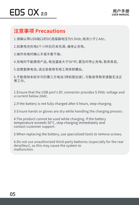
- Ensure that the USB port's DC connector provides 5.0Vdc voltage and a current below 2Adc.
- If the battery is not fully charged after 6 hours, stop charging.
- Ensure hands or gloves are dry while handling the charging process.
- The product cannot be used while charging. If the battery temperature exceeds 50°C, stop charging immediately and contact customer support.
- When replacing the battery, use specialized tools to remove screws.
- Do not use unauthorized third-party batteries (especially for the rear derailleur), as this may cause the system to malfunction.
System Pairing
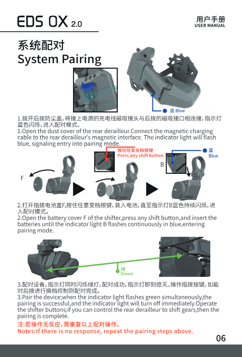
- Open the dust cover of the rear derailleur. Connect the magnetic charging cable to the rear derailleur's magnetic interface. The indicator light will flash blue, signaling entry into pairing mode.
- Open the shifter's battery cover (F), press any shift button, and insert the batteries until the indicator light (B) flashes continuously in blue, entering pairing mode.
- Pair the devices; when the indicator lights flash green simultaneously, pairing is successful and the lights will turn off immediately. Operate the shifter buttons — if you can control the rear derailleur to shift gears, pairing is complete.
Note: If there is no response, repeat the pairing steps above.
Pairing Precautions
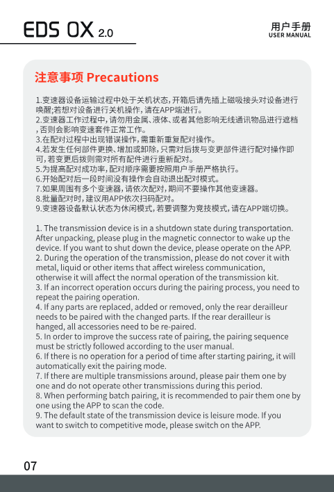
- The transmission device is in a shutdown state during transportation. After unboxing, plug in the magnetic connector to wake up the device. If you want to shut down the device, do so via the app.
- During pairing, do not cover the transmission with metal, liquid, or other items that affect wireless communication, otherwise it will affect normal operation of the kit.
- If an incorrect operation occurs during pairing, repeat the pairing procedure.
- If any part is replaced, added, or removed, only the rear derailleur and the changed part need to be re-paired. If the rear derailleur itself is replaced, all accessories need to be re-paired.
- To improve pairing success rate, the pairing sequence must be strictly followed according to the user manual.
- If there is no operation for a period of time after starting pairing, the device automatically exits pairing mode.
- If there are multiple transmissions nearby, pair them one by one and do not operate other transmissions during this period.
- When performing batch pairing, it is recommended to pair them one by one using the APP to scan the code.
- The default state of the transmission device is Leisure Mode. If you want to switch to Competitive (Sport) Mode, please switch it in the APP.
Installation
Shifter Installation
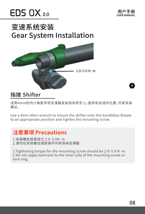
Use a 4mm Allen wrench to mount the shifter onto the handlebar. Rotate it to an appropriate position and tighten the mounting screw.
- Tightening torque for the mounting screw should be 2.0–5.0 N·m.
- Do not apply lubricant to the inner side of the mounting screw or the lock ring.
Rear Derailleur Installation
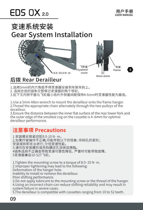
- Use a 5mm Allen wrench to mount the derailleur onto the frame hanger.
- Thread the appropriate chain alternately through the two pulleys of the derailleur.
- Ensure the distance between the inner flat surface of the rear lower fork and the outer edge of the smallest cog on the cassette is 4–6mm for optimal derailleur performance.
- Tighten the mounting screw to a torque of 8.0–10 N·m.
- Improper tightening may lead to: deformation of the hanger hole; inability to install or remove the derailleur; poor shifting performance.
- Do not apply lubricant to the mounting screw or the hanger thread.
- Using an incorrect chain can reduce shifting reliability and may cause system failure in severe cases.
- The derailleur is compatible with cassettes ranging from 10 to 52 teeth.
Derailleur Calibration
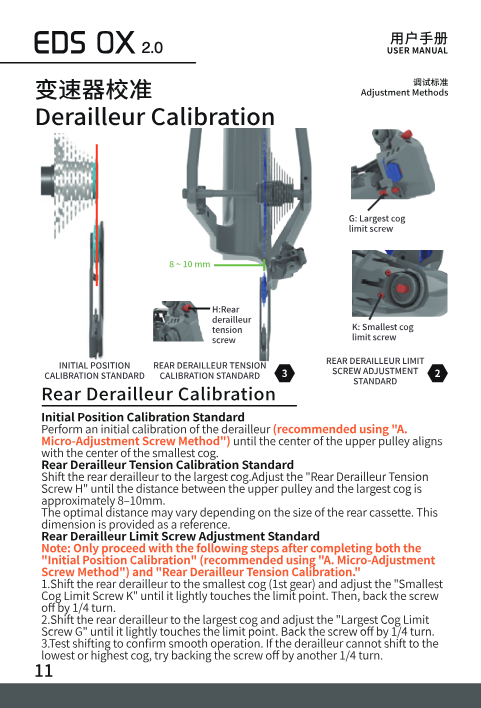
Initial Position Calibration Standard: Perform an initial calibration of the derailleur (recommended using the "A. Micro-Adjustment Screw Method" below) until the center of the upper pulley aligns with the center of the smallest cog.
Rear Derailleur Tension Calibration Standard: Shift the rear derailleur to the largest cog. Adjust the Rear Derailleur Tension Screw (H) until the distance between the upper pulley and the largest cog is approximately 8–10mm. The optimal distance may vary depending on the size of the rear cassette; this dimension is provided as a reference.
Rear Derailleur Limit Screw Adjustment Standard: Only proceed with the following steps after completing both the Initial Position Calibration and the Rear Derailleur Tension Calibration.
- Shift the rear derailleur to the smallest cog (1st gear) and adjust the Smallest Cog Limit Screw (K) until it lightly touches the limit point. Then back the screw off by 1/4 turn.
- Shift the rear derailleur to the largest cog and adjust the Largest Cog Limit Screw (G) until it lightly touches the limit point. Back the screw off by 1/4 turn.
- Test shifting to confirm smooth operation. If the derailleur cannot shift to the lowest or highest cog, try backing the corresponding screw off by another 1/4 turn.
Method A — Micro-Adjustment Screw Method (Initial Calibration)
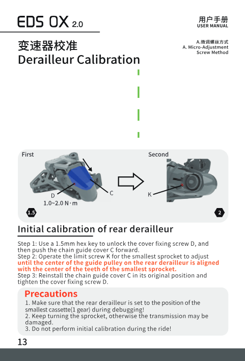
- Use a 1.5mm hex key to loosen the cover fixing screw (D), then push the chain guide cover (C) forward.
- Turn the smallest cog limit screw (K) until the center of the rear derailleur's upper pulley aligns with the center of the teeth of the smallest cog.
- Reinstall the chain guide cover (C) in its original position and tighten the cover fixing screw (D).
Precautions: Make sure the rear derailleur is set to the smallest cassette (1st gear) position during calibration. Keep turning the crank, otherwise the derailleur may be damaged. Do not perform initial calibration while riding.
Method B — App-Based Adjustment (Initial Calibration)
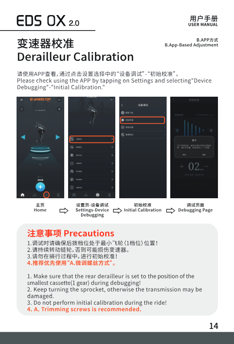
In the app, go to Settings → Device Debugging → Initial Calibration to open the debugging page.
Precautions: Make sure the rear derailleur is set to the smallest cassette (1st gear) position during calibration. Keep turning the crank, otherwise the derailleur may be damaged. Do not perform initial calibration while riding. Method A (micro-adjustment screw) is recommended for precise calibration.
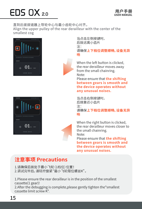
Align the upper pulley of the rear derailleur with the center of the smallest cog. When the left button is pressed, the rear derailleur moves away from the smallest cog; when the right button is pressed, it moves closer. In both cases, confirm that shifting between gears is smooth and the device operates without unusual noises.
Precautions: Ensure the rear derailleur is in the smallest cassette (1st gear) position. After debugging is complete, gently tighten the smallest cassette limit screw (K).
Method C — Handle (Shifter) Micro-Adjustment
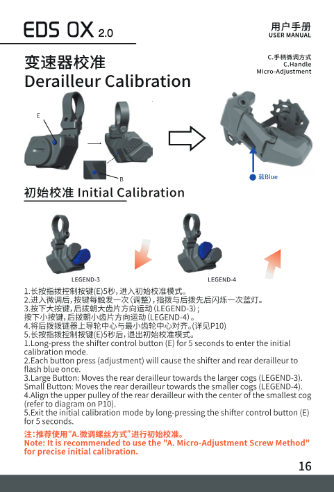
- Long-press the shifter's control button (E) for 5 seconds to enter initial calibration mode.
- Each button press causes the shifter and rear derailleur indicator lights to flash blue once.
- Large button: moves the rear derailleur towards the larger cogs. Small button: moves the rear derailleur towards the smaller cogs.
- Align the upper pulley of the rear derailleur with the center of the smallest cog.
- Exit initial calibration mode by long-pressing the control button (E) for 5 seconds.
Note: The Micro-Adjustment Screw Method (Method A) is recommended for precise initial calibration.
Rear Derailleur Tension Screw Adjustment
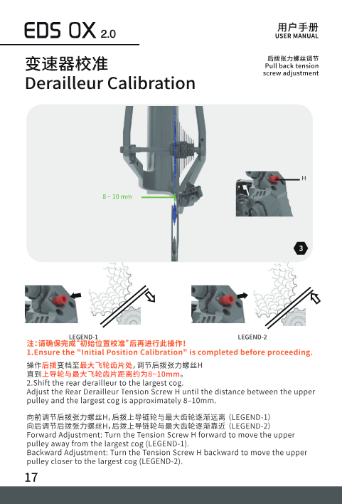
Ensure the Initial Position Calibration is completed before proceeding. Shift the rear derailleur to the largest cog and adjust the Rear Derailleur Tension Screw (H) until the distance between the upper pulley and the largest cog is approximately 8–10mm.
Forward adjustment: turn the tension screw (H) forward to move the upper pulley away from the largest cog. Backward adjustment: turn the tension screw (H) backward to move the upper pulley closer to the largest cog.
Limit Screw Adjustment
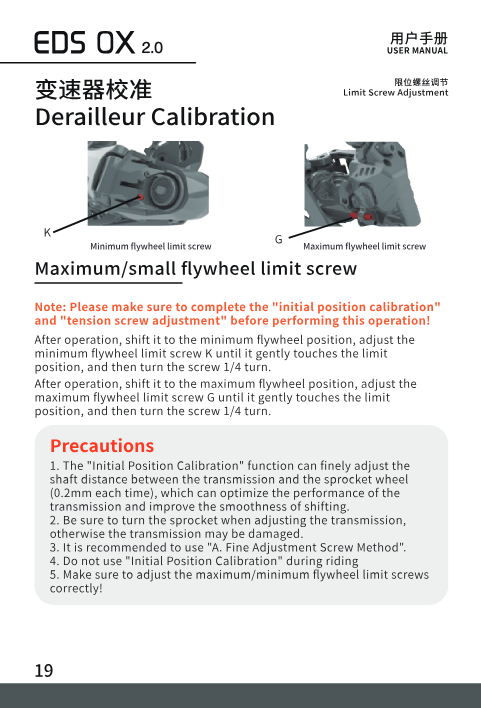
Complete both the Initial Position Calibration and Tension Screw Adjustment before performing this operation.
- Shift the rear derailleur to the smallest cassette position and adjust the minimum cassette limit screw (K) until it gently touches the limit point, then turn the screw back 1/4 turn.
- Shift the rear derailleur to the largest cassette position and adjust the maximum cassette limit screw (G) until it gently touches the limit point, then turn the screw back 1/4 turn.
Precautions: The Initial Position Calibration can finely adjust the distance between the derailleur and the cassette in steps of 0.2mm, improving shifting performance and smoothness. Keep turning the crank while adjusting, otherwise the derailleur may be damaged. The Micro-Adjustment Screw Method is recommended. Do not perform Initial Position Calibration while riding. Make sure to adjust the maximum/minimum cassette limit screws correctly.
Derailleur Adjustments
Fine-Tuning Gear Positions (App)
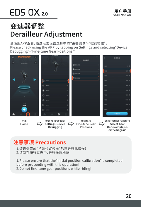
In the app, go to Settings → Device Debugging → Fine-Tune Gear Positions, then select the gear (for example, "2nd gear").
Precautions: Ensure the Initial Position Calibration is completed before performing this operation. Do not fine-tune gear positions while riding.
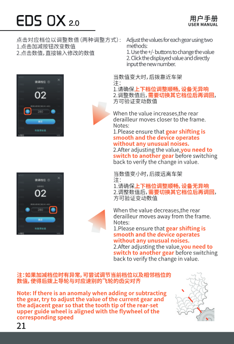
Adjust the value for each gear using either method: use the +/− buttons to change the value, or tap the displayed value to type in a new number directly.
When the value increases, the rear derailleur moves closer to the frame. When the value decreases, it moves away from the frame. In both cases, confirm that shifting is smooth and the device operates without unusual noises — after adjusting a value, switch to another gear and back again to verify the change took effect.
Note: If shifting is abnormal after increasing or decreasing a gear's value, try adjusting the value for both the current gear and the adjacent gear so the upper pulley aligns with the corresponding cog.
Shifting Operations
Up-shifting (Increase Gears)
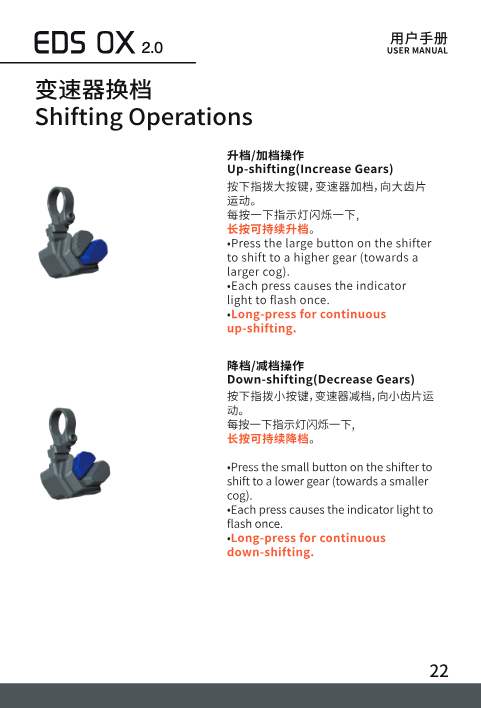
Press the large button on the shifter to shift to a higher gear (towards a larger cog). Each press causes the indicator light to flash once. Long-press for continuous up-shifting.
Down-shifting (Decrease Gears)
Press the small button on the shifter to shift to a lower gear (towards a smaller cog). Each press causes the indicator light to flash once. Long-press for continuous down-shifting.
Free Configuration of Shifting (App)
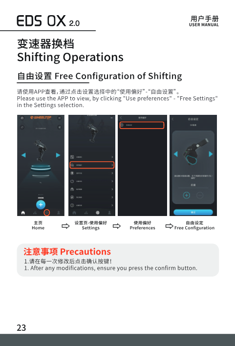
In the app, go to Settings → Use Preferences → Free Configuration.
Precautions: After any modifications, be sure to press the confirm button.
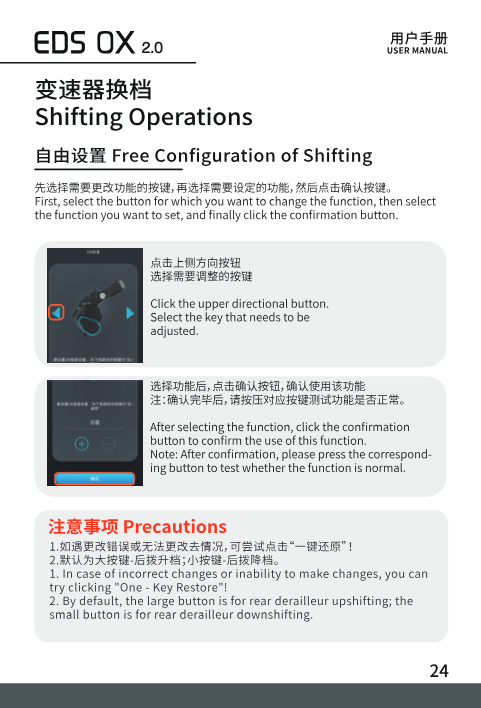
First, select the button whose function you want to change, then select the function you want to assign, and finally tap the confirmation button. After confirming, press the corresponding button to test whether the function works normally.
Precautions: If you make an incorrect change or cannot make changes, try "One-Key Restore." By default, the large button controls rear derailleur up-shifting and the small button controls rear derailleur down-shifting.
Indicator Light Overview
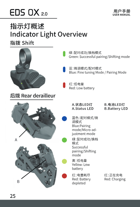
Shifter LED: Green = successful pairing / shifting mode; Blue = fine-tuning mode / pairing mode; Red = low battery.
Rear derailleur status LED: Blue = pairing mode / micro-adjustment mode; Green = successful pairing / shifting mode; Yellow = low battery; Red = battery depleted.
Rear derailleur battery LED: Red = charging; off = charging complete.
Maintenance
Shifter Battery
Use a coin to rotate and open the shifter's battery cover, remove the used battery, insert a new CR2032 battery, snap it in, and tighten the battery cover.
Accessory Replacement
If either the rear derailleur or the shifter is damaged and needs to be replaced separately, refer to the shifter installation or rear derailleur installation sections above. Any accessory replacement requires re-pairing.
- Only CR2032 batteries can be used for the shifter.
- It is recommended to clean the derailleur regularly.
- The derailleur's operating temperature range is −10°C to 50°C.
- The rear derailleur's battery is an integrated, non-removable design — non-professionals should not disassemble it. Air transport requiring disassembly must be handled by a professional.
Need Help?
For anything not covered here — pairing errors, calibration issues, or a suspected fault — contact us and we'll walk you through it. As an authorized WHEELTOP partner, we provide hands-on installation and tuning support for every EDS OX 2.0 order.
