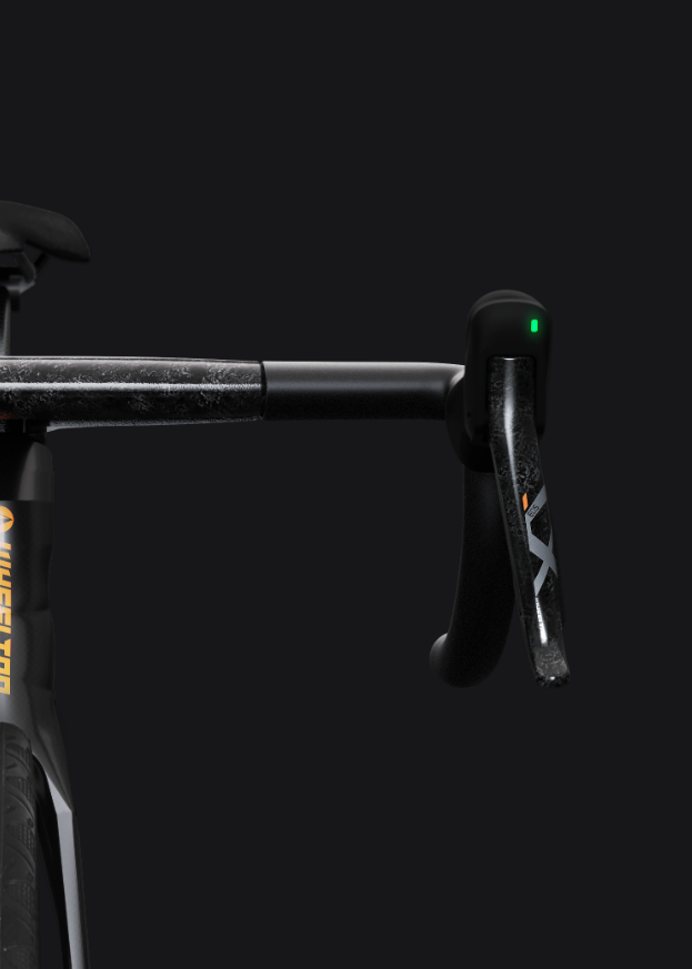
WHEELTOP EDS TX — Installation, Pairing & Calibration Manual
← Back to User ManualsOn this page
This is a complete page-by-page reproduction of the official WHEELTOP EDS TX User Manual V3.0.1 — every diagram and instruction from the printed PDF, rebuilt as a searchable web page. For the original file, use the PDF download in the sidebar.

WHEELTOP EDS TX — Wireless Electronic Shifting System
User Manual V3.0.1
Contact & App
Lanxi Wheel Top Cycle Industries Co., Ltd.
TEL: +86(579) 83881076 / 83888356
Download the WHEELTOP App
Search "WHEEL TOP" on Google Play or the App Store to download the app.
Important Notice
For safety reasons, please read this user manual carefully and follow the instructions for correct use before using the product.
Safety Instructions
You must read and understand the safety instructions accompanying the product before installation. Improper installation of components is extremely dangerous and may cause serious or even fatal personal injury. If you have any questions about component installation, please consult a professional bicycle mechanic.
Note
This manual is a complete system installation guide, covering the entire process from unboxing each component to starting your ride. Follow the sequence described in this manual to complete the corresponding installation and setup. Only begin the next step after completing the previous one. For the sales regions of this product, please refer to the official website explanation. Sales in unauthorized regions are at your own risk.
This device complies with Part 15 of the FCC Rules.
Operation Requirements: (1) This device may not cause harmful interference. (2) This device must accept any interference received, including interference that may cause undesired operation. Any changes or modifications not expressly approved by the party responsible for compliance could void the user's authority to operate the equipment.
FCC Compliance: This device has been tested and found to comply with the limits for a Class B digital device, pursuant to Part 15 of the FCC Rules. If this equipment causes harmful interference to radio or television reception, try reorienting the receiving antenna, increasing separation between equipment and receiver, connecting the equipment to a different outlet circuit, or consulting the dealer or an experienced radio/TV technician.
This equipment complies with FCC radiation exposure limits for an uncontrolled environment and should be operated with a minimum distance of 20cm between the radiator and your body.
Safety & Before You Start
Before Installation and Calibration, Please Confirm
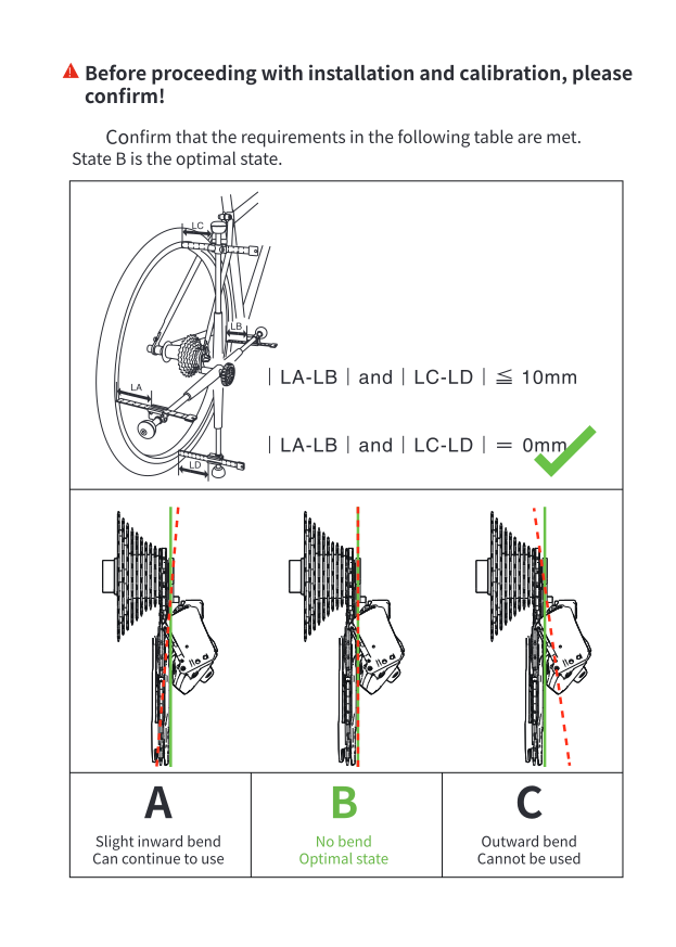
Confirm your frame and derailleur hanger meet the requirements below before installing or calibrating. State B is the optimal state.
- State A — slight inward bend: |LA−LB| and |LC−LD| ≤ 10mm. Can continue to use.
- State B — no bend (optimal): |LA−LB| and |LC−LD| = 0mm.
- State C — outward bend: cannot be used.
Tools Required
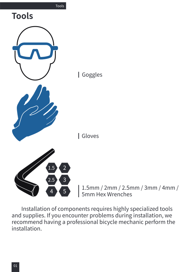
- Safety goggles
- Gloves
- 1.5mm / 2mm / 2.5mm / 3mm / 4mm / 5mm hex wrenches
Installation of components requires highly specialized tools and supplies. If you encounter problems during installation, we recommend having a professional bicycle mechanic perform the installation.
Component Overview
Dual-Control Shifter
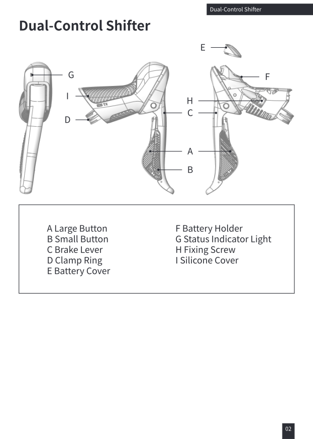
A. Large Button B. Small Button C. Brake Lever D. Clamp Ring E. Battery Cover F. Battery Holder G. Status Indicator Light H. Fixing Screw I. Silicone Cover
Front Derailleur
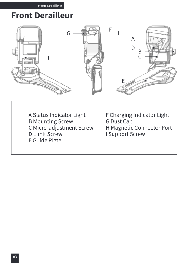
A. Status Indicator Light B. Mounting Screw C. Micro-adjustment Screw D. Limit Screw E. Guide Plate F. Charging Indicator Light G. Dust Cap H. Magnetic Connector Port I. Support Screw
Rear Derailleur
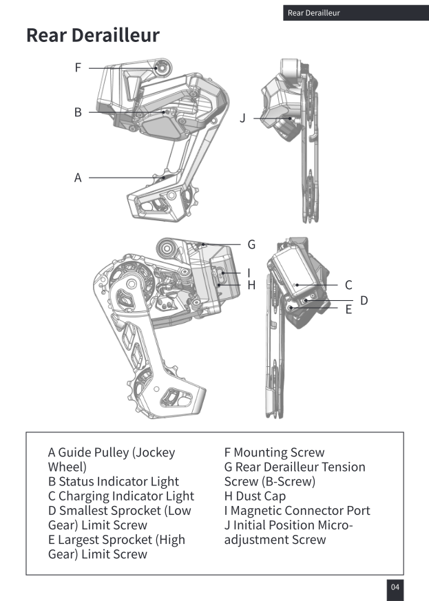
A. Guide Pulley (Jockey Wheel) B. Status Indicator Light C. Charging Indicator Light D. Smallest Sprocket (Low Gear) Limit Screw E. Largest Sprocket (High Gear) Limit Screw F. Mounting Screw G. Rear Derailleur Tension Screw (B-Screw) H. Dust Cap I. Magnetic Connector Port J. Initial Position Micro-adjustment Screw
How Shifting Works
Rear Derailleur Shifting
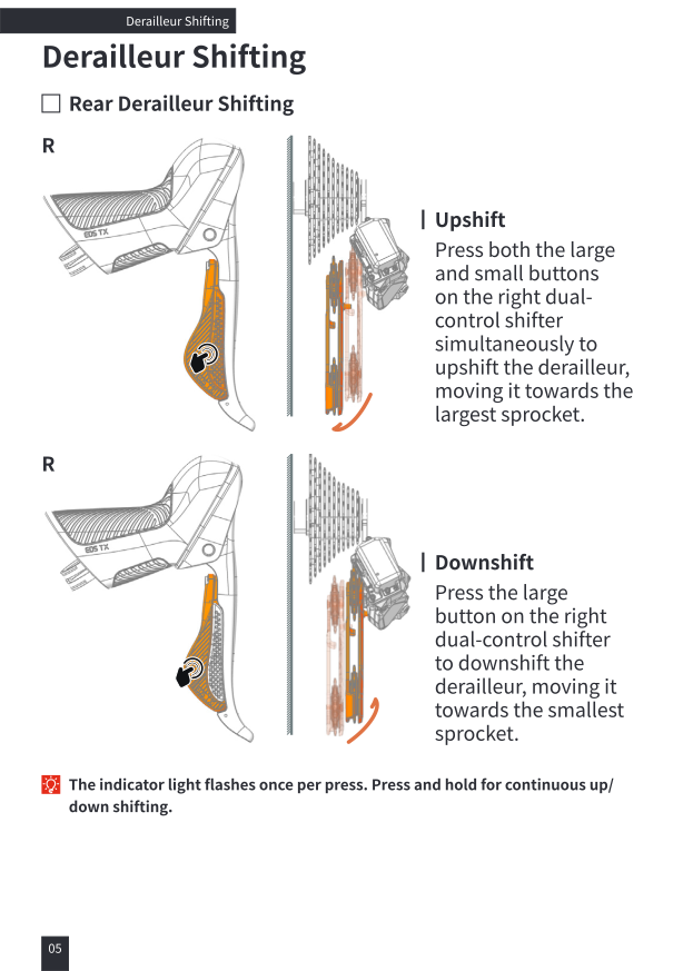
Upshift: press both the large and small buttons on the right dual-control shifter simultaneously to upshift the derailleur, moving it towards the largest sprocket.
Downshift: press the large button on the right dual-control shifter to downshift the derailleur, moving it towards the smallest sprocket.
The indicator light flashes once per press. Press and hold for continuous up/down shifting.
Front Derailleur Shifting
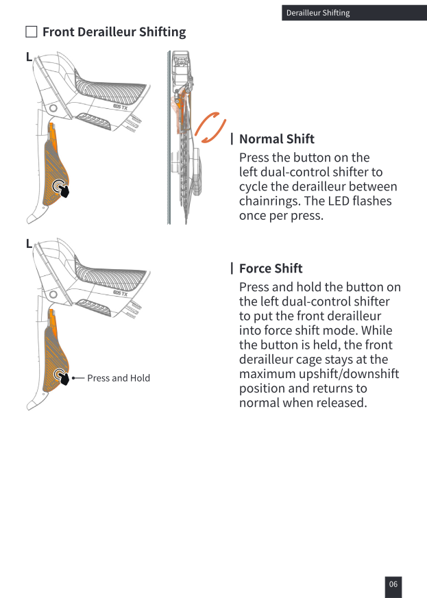
Normal Shift: press the button on the left dual-control shifter to cycle the derailleur between chainrings. The LED flashes once per press.
Force Shift: press and hold the button on the left dual-control shifter to put the front derailleur into force shift mode. While the button is held, the front derailleur cage stays at the maximum upshift/downshift position and returns to normal when released.
Charging
Front Derailleur / Rear Derailleur Charging
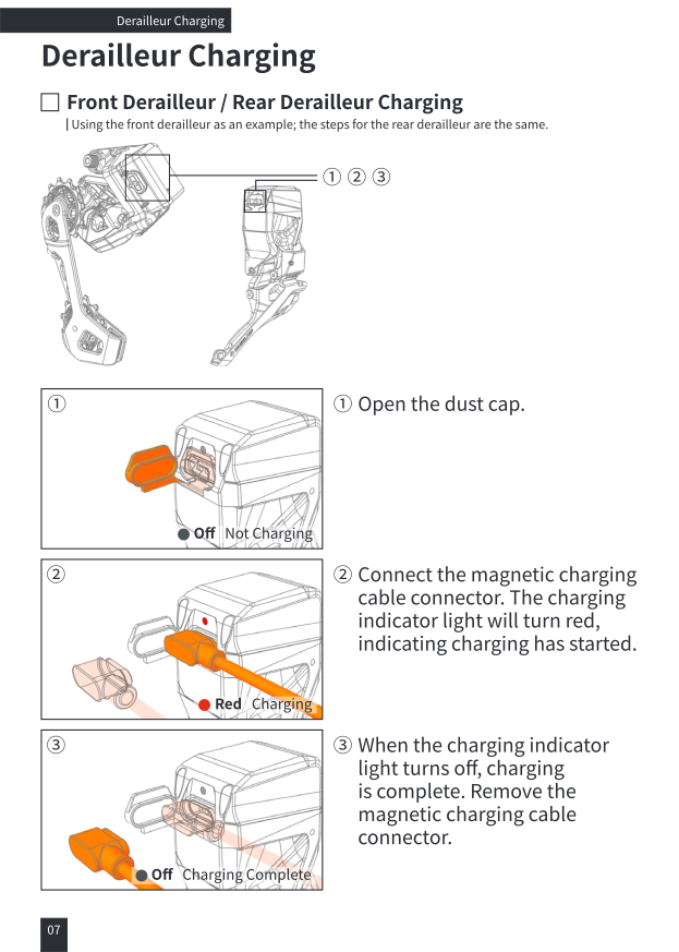
Using the front derailleur as an example; the steps for the rear derailleur are the same.
- Open the dust cap. (Off = Not Charging)
- Connect the magnetic charging cable connector. The charging indicator light turns red, indicating charging has started.
- When the charging indicator light turns off, charging is complete. Remove the magnetic charging cable connector.
Charging Precautions
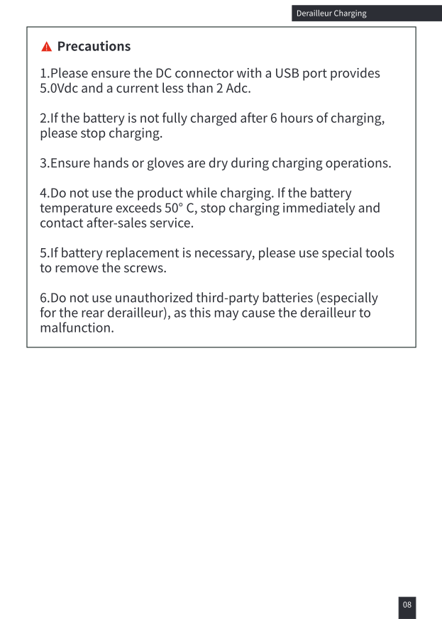
- Ensure the DC connector with a USB port provides 5.0Vdc and a current less than 2 Adc.
- If the battery is not fully charged after 6 hours of charging, please stop charging.
- Ensure hands or gloves are dry during charging operations.
- Do not use the product while charging. If the battery temperature exceeds 50°C, stop charging immediately and contact after-sales service.
- If battery replacement is necessary, please use special tools to remove the screws.
- Do not use unauthorized third-party batteries (especially for the rear derailleur), as this may cause the derailleur to malfunction.
Dual-Control Shifter Battery Installation
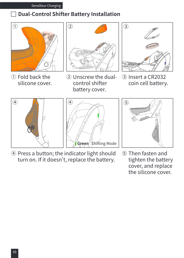
- Fold back the silicone cover.
- Unscrew the dual-control shifter battery cover.
- Insert a CR2032 coin cell battery.
- Press a button; the indicator light should turn on (green = shifting mode). If it doesn't, replace the battery.
- Fasten and tighten the battery cover, and replace the silicone cover.
System Pairing
1. Entering Pairing Mode for Rear Derailleur
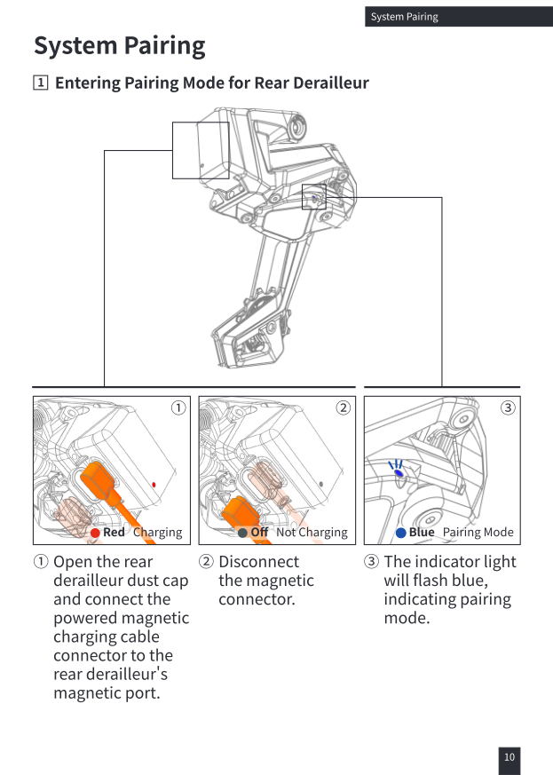
- Open the rear derailleur dust cap and connect the powered magnetic charging cable connector to the rear derailleur's magnetic port. (Red = Charging)
- Disconnect the magnetic connector. (Off = Not Charging)
- The indicator light will flash blue, indicating pairing mode.
2. Front Derailleur Entering Pairing Mode
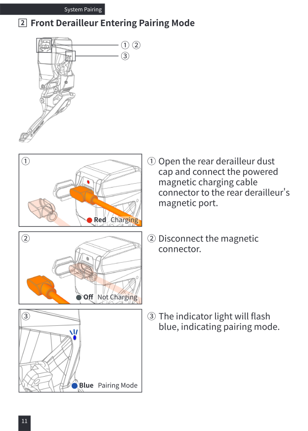
- Open the front derailleur dust cap and connect the powered magnetic charging cable connector to the front derailleur's magnetic port. (Red = Charging)
- Disconnect the magnetic connector. (Off = Not Charging)
- The indicator light will flash blue, indicating pairing mode.
Corrected from the original PDF, which mistakenly repeats "rear derailleur" in this step's caption.
3. Front Derailleur and Rear Derailleur Pairing
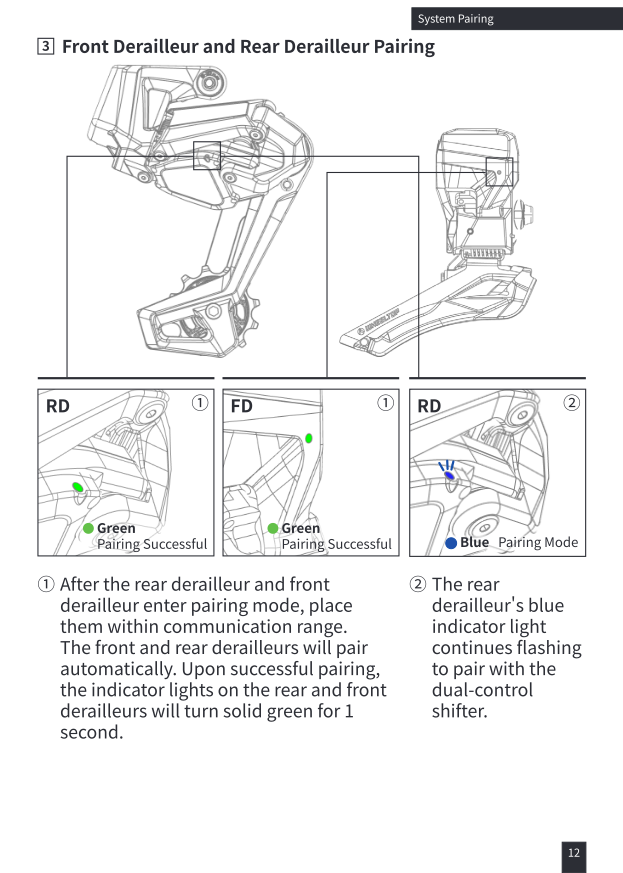
- After the rear derailleur and front derailleur enter pairing mode, place them within communication range. The front and rear derailleurs will pair automatically. Upon successful pairing, the indicator lights on the rear and front derailleurs will turn solid green for 1 second.
- The rear derailleur's blue indicator light continues flashing to pair with the dual-control shifter.
4. Dual-Control Shifter Entering Pairing Mode
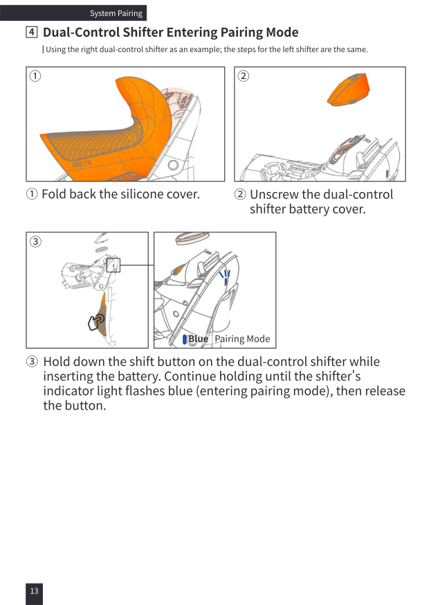
Using the right dual-control shifter as an example; the steps for the left shifter are the same.
- Fold back the silicone cover.
- Unscrew the dual-control shifter battery cover.
- Hold down the shift button on the dual-control shifter while inserting the battery. Continue holding until the shifter's indicator light flashes blue (entering pairing mode), then release the button.
5. Dual-Control Shifter and Rear Derailleur Pairing
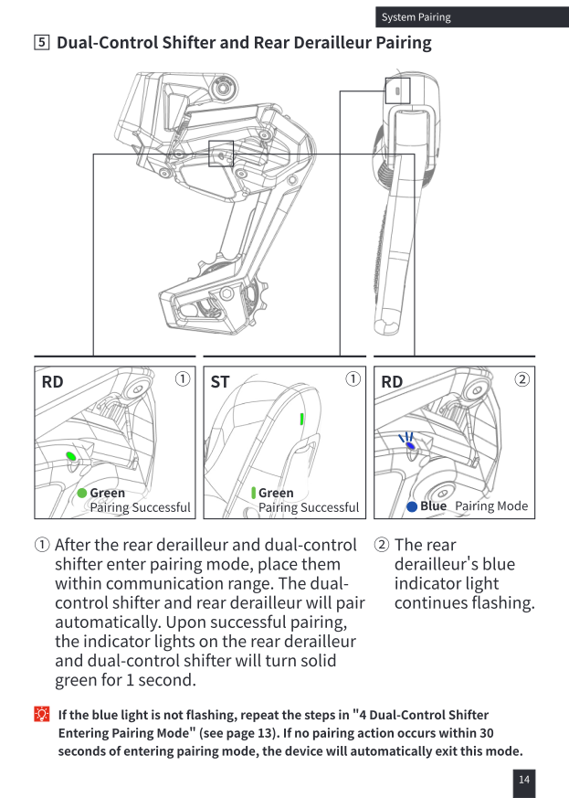
- After the rear derailleur and dual-control shifter enter pairing mode, place them within communication range. The dual-control shifter and rear derailleur will pair automatically. Upon successful pairing, the indicator lights on the rear derailleur and dual-control shifter will turn solid green for 1 second.
- The rear derailleur's blue indicator light continues flashing.
If the blue light is not flashing, repeat the steps in "Dual-Control Shifter Entering Pairing Mode". If no pairing action occurs within 30 seconds of entering pairing mode, the device will automatically exit this mode.
6. Exiting Pairing Mode
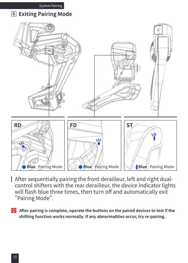
After sequentially pairing the front derailleur, left and right dual-control shifters with the rear derailleur, the device indicator lights will flash blue three times, then turn off and automatically exit "Pairing Mode".
After pairing is complete, operate the buttons on the paired devices to test if the shifting function works normally. If any abnormalities occur, try re-pairing.
Pairing Precautions
- The derailleur devices are powered off during transportation. After unboxing, please charge them first to wake up the devices. To power off a device, please use the app.
- Before unboxing, the derailleur kit has already been paired; re-pairing is not necessary.
- During derailleur operation, do not obstruct the derailleurs with metal, liquid, or other items that may affect wireless communication.
- If an error occurs during the pairing process, re-perform the pairing operation.
- If any component is replaced, added, or removed, only the rear derailleur and the changed component need to be re-paired. If the rear derailleur is replaced, all components need to be re-paired.
- To improve pairing success rate, the pairing sequence must be strictly followed as per the user manual.
- If there are multiple derailleur systems nearby, pair the components one by one, and do not operate other derailleurs during this process.
- The derailleur device defaults to "Leisure Mode". To switch to "Sport Mode", please change it in the app.
Installation
Dual-Control Shifter Installation
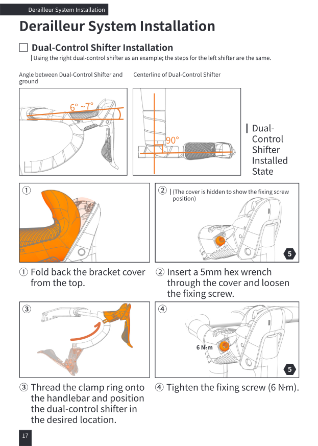
Using the right dual-control shifter as an example; the steps for the left shifter are the same. Target geometry: shifter angled 6°–7° from the ground, centerline at 90° to the handlebar.
- Fold back the bracket cover from the top.
- Insert a 5mm hex wrench through the cover and loosen the fixing screw.
- Thread the clamp ring onto the handlebar and position the dual-control shifter in the desired location.
- Tighten the fixing screw (6 N·m).
Front Derailleur Installation
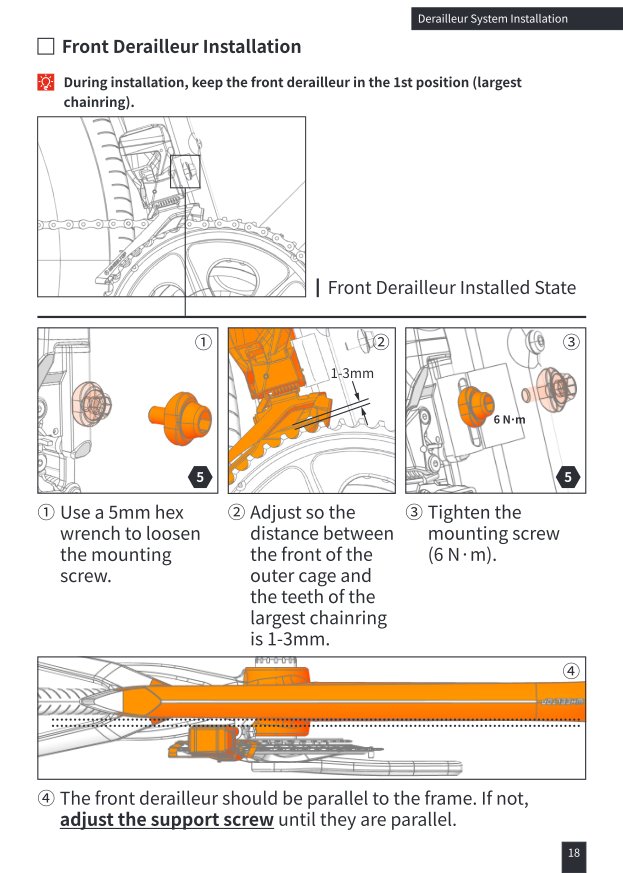
During installation, keep the front derailleur in the 1st position (largest chainring).
- Use a 5mm hex wrench to loosen the mounting screw.
- Adjust so the distance between the front of the outer cage and the teeth of the largest chainring is 1–3mm.
- Tighten the mounting screw (6 N·m).
- The front derailleur should be parallel to the frame. If not, adjust the support screw until they are parallel.
Adjusting the Support Screw
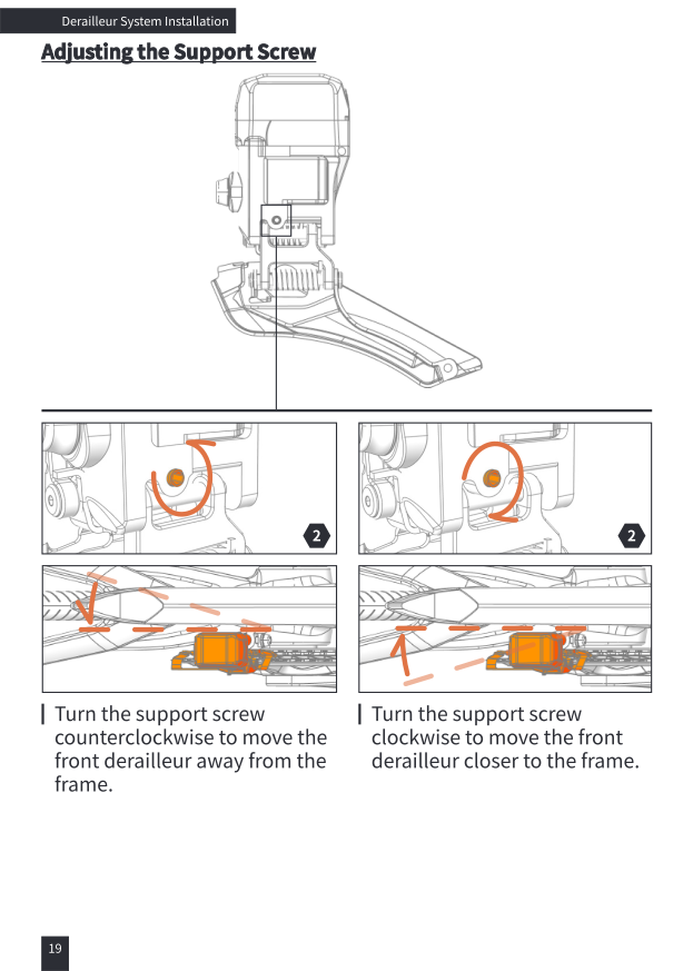
Turn the support screw counterclockwise to move the front derailleur away from the frame. Turn the support screw clockwise to move the front derailleur closer to the frame.
Rear Derailleur Installation
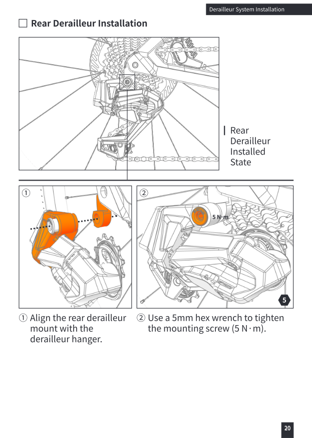
- Align the rear derailleur mount with the derailleur hanger.
- Use a 5mm hex wrench to tighten the mounting screw (5 N·m).
Chain Installation — Check Chain Length
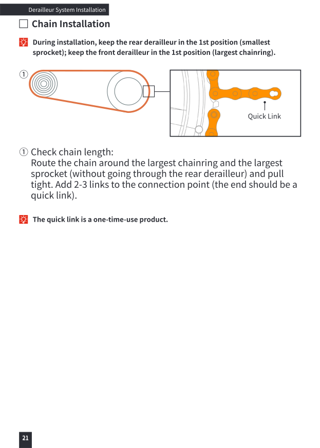
During installation, keep the rear derailleur in the 1st position (smallest sprocket); keep the front derailleur in the 1st position (largest chainring).
Route the chain around the largest chainring and the largest sprocket (without going through the rear derailleur) and pull tight. Add 2–3 links to the connection point (the end should be a quick link). The quick link is a one-time-use product.
Chain Installation — Routing
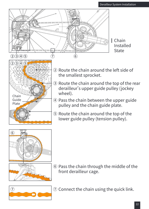
- Route the chain around the left side of the smallest sprocket.
- Route the chain around the top of the rear derailleur's upper guide pulley (jockey wheel).
- Pass the chain between the upper guide pulley and the chain guide plate.
- Route the chain around the top of the lower guide pulley (tension pulley).
- Pass the chain through the middle of the front derailleur cage.
- Connect the chain using the quick link.
Calibration
Initial Calibration
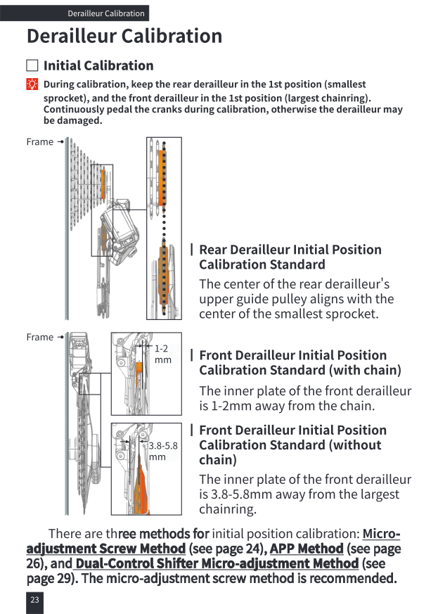
During calibration, keep the rear derailleur in the 1st position (smallest sprocket), and the front derailleur in the 1st position (largest chainring). Continuously pedal the cranks during calibration, otherwise the derailleur may be damaged.
- Rear derailleur: the center of the upper guide pulley aligns with the center of the smallest sprocket.
- Front derailleur (with chain): the inner plate is 1–2mm away from the chain.
- Front derailleur (without chain): the inner plate is 3.8–5.8mm away from the largest chainring.
There are three methods for initial position calibration: Micro-adjustment Screw Method, App Method, and Dual-Control Shifter Micro-adjustment Method. The micro-adjustment screw method is recommended.
Method 1 — Micro-Adjustment Screw (Rear Derailleur)
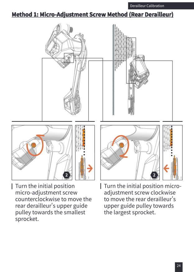
Turn the initial position micro-adjustment screw counterclockwise to move the rear derailleur's upper guide pulley towards the smallest sprocket. Turn it clockwise to move towards the largest sprocket.
Method 1 — Micro-Adjustment Screw (Front Derailleur)
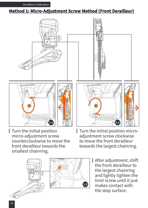
Turn the initial position micro-adjustment screw counterclockwise to move the front derailleur towards the smallest chainring. Turn it clockwise to move towards the largest chainring.
After adjustment, shift the front derailleur to the largest chainring and lightly tighten the limit screw until it just makes contact with the stop surface.
Method 2 — App Method: Device Binding
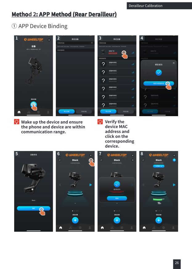
Wake up the device and ensure the phone and device are within communication range. Verify the device MAC address and tap the corresponding device to bind it.
Method 2 — App Method: Rear Derailleur Calibration
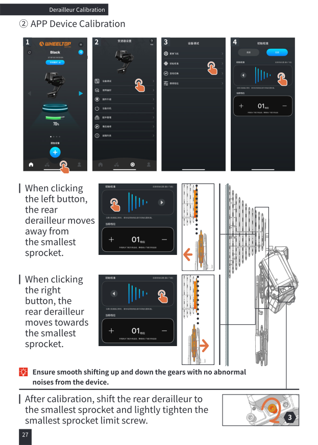
When clicking the left button, the rear derailleur moves away from the smallest sprocket. When clicking the right button, the rear derailleur moves towards the smallest sprocket. Ensure smooth shifting up and down the gears with no abnormal noises from the device.
After calibration, shift the rear derailleur to the smallest sprocket and lightly tighten the smallest sprocket limit screw.
Method 2 — App Method: Front Derailleur Calibration
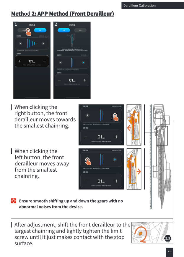
When clicking the right button, the front derailleur moves towards the smallest chainring. When clicking the left button, the front derailleur moves away from the smallest chainring.
After adjustment, shift the front derailleur to the largest chainring and lightly tighten the limit screw until it just makes contact with the stop surface.
Method 3 — Shifter Micro-adjustment (Rear Derailleur), Entering Calibration Mode
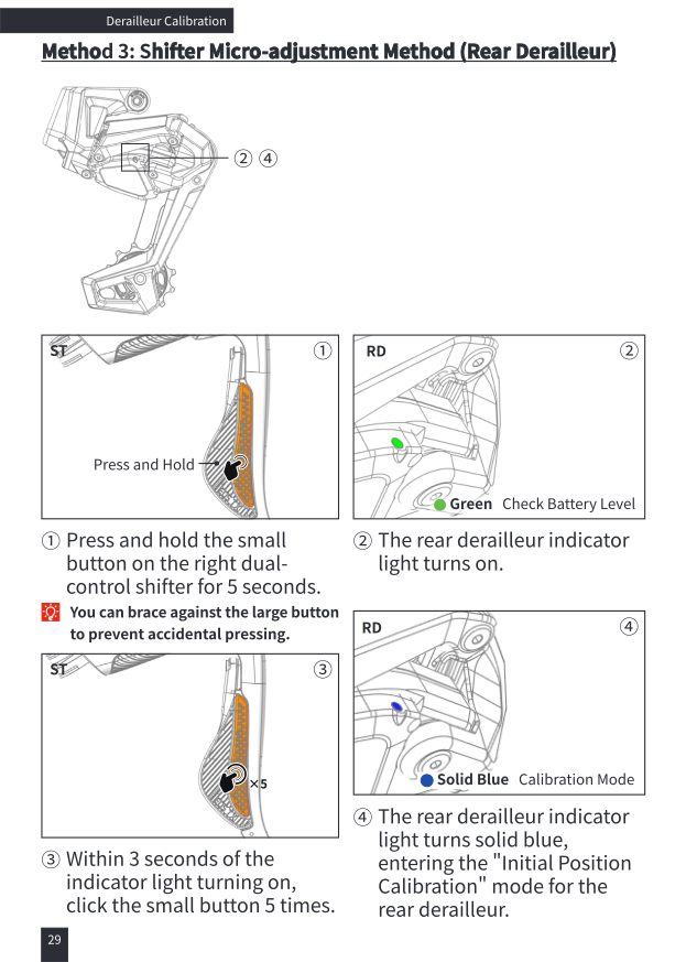
- Press and hold the small button on the right dual-control shifter for 5 seconds. (You can brace against the large button to prevent accidental pressing.)
- The rear derailleur indicator light turns on (green = check battery level).
- Within 3 seconds of the indicator light turning on, click the small button 5 times.
- The rear derailleur indicator light turns solid blue, entering the "Initial Position Calibration" mode for the rear derailleur.
Method 3 — Shifter Micro-adjustment (Rear Derailleur), Adjusting
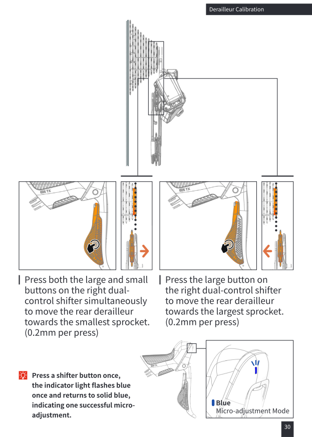
Press the large button on the right dual-control shifter to move the rear derailleur towards the largest sprocket (0.2mm per press). Press both the large and small buttons together to move it towards the smallest sprocket (0.2mm per press).
Press a shifter button once — the indicator light flashes blue once and returns to solid blue, indicating one successful micro-adjustment.
Method 3 — Shifter Micro-adjustment (Front Derailleur), Switching Device
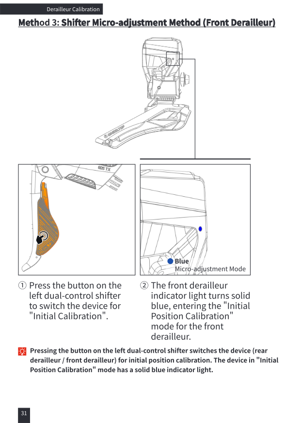
Pressing the button on the left dual-control shifter switches the device (rear derailleur / front derailleur) for initial position calibration. The device in "Initial Position Calibration" mode has a solid blue indicator light.
Method 3 — Shifter Micro-adjustment (Front Derailleur), Adjusting & Exiting
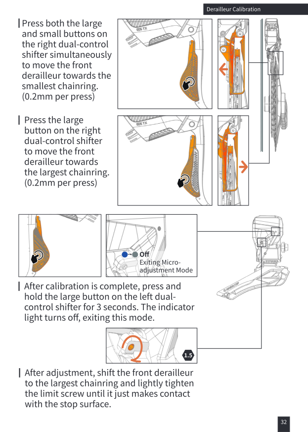
Press the large button on the right dual-control shifter to move the front derailleur towards the largest chainring (0.2mm per press). Press both the large and small buttons together to move it towards the smallest chainring (0.2mm per press).
After calibration is complete, press and hold the large button on the left dual-control shifter for 3 seconds. The indicator light turns off, exiting this mode.
After adjustment, shift the front derailleur to the largest chainring and lightly tighten the limit screw until it just makes contact with the stop surface.
Rear Derailleur Tension (B-Screw) Calibration
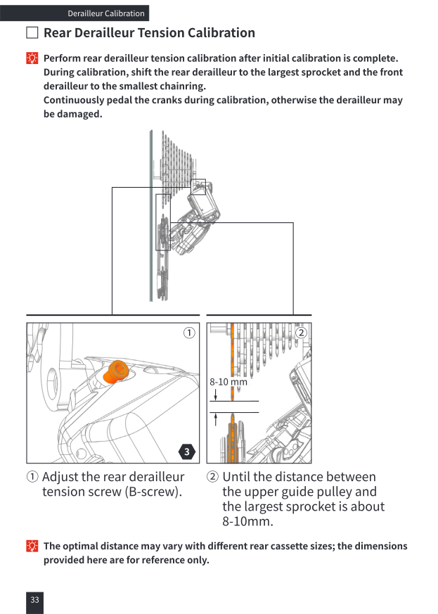
Perform rear derailleur tension calibration after initial calibration is complete. During calibration, shift the rear derailleur to the largest sprocket and the front derailleur to the smallest chainring. Continuously pedal the cranks during calibration.
Adjust the rear derailleur tension screw (B-screw) until the distance between the upper guide pulley and the largest sprocket is about 8–10mm. The optimal distance may vary with different rear cassette sizes; the dimension given is for reference only.
Rear Derailleur Limit Screw Calibration
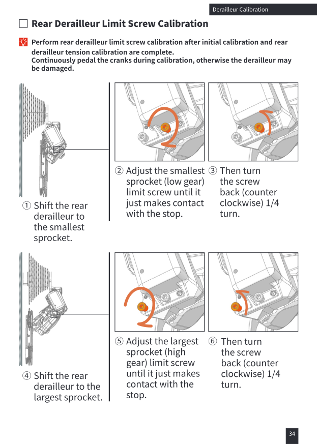
Perform this after initial calibration and tension calibration are complete. Continuously pedal the cranks during calibration.
- Shift the rear derailleur to the smallest sprocket. Adjust the smallest sprocket (low gear) limit screw until it just makes contact with the stop, then turn it back (counterclockwise) 1/4 turn.
- Shift the rear derailleur to the largest sprocket. Adjust the largest sprocket (high gear) limit screw until it just makes contact with the stop, then turn it back 1/4 turn.
Rear Derailleur Limit Screw — Test Shifting
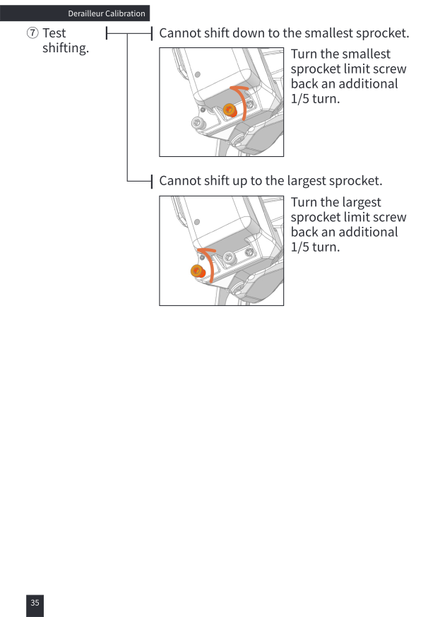
Test shifting through the full range: if it cannot shift down to the smallest sprocket, turn the smallest sprocket limit screw back an additional 1/5 turn. If it cannot shift up to the largest sprocket, turn the largest sprocket limit screw back an additional 1/5 turn.
Gear Micro-adjustment
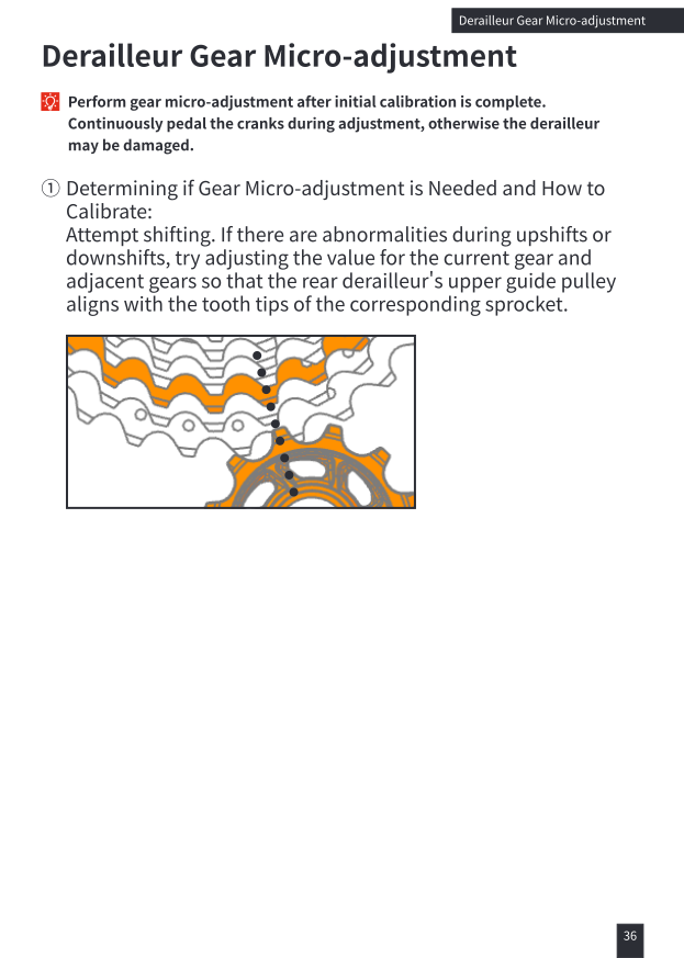
Perform gear micro-adjustment after initial calibration is complete. Continuously pedal the cranks during adjustment, otherwise the derailleur may be damaged.
Attempt shifting. If there are abnormalities during upshifts or downshifts, try adjusting the value for the current gear and adjacent gears so that the rear derailleur's upper guide pulley aligns with the tooth tips of the corresponding sprocket.
Gear Micro-adjustment Method
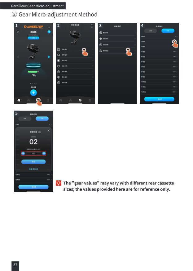
In the app: Device Settings → Device Debug → Micro-adjust Gears, then select the gear to tune. Each gear has an adjustable value in the range 60–460. The "gear values" may vary with different rear cassette sizes; the values given are for reference only.
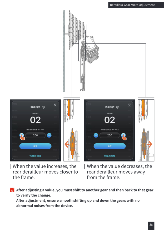
When the value increases, the rear derailleur moves closer to the frame. When the value decreases, the rear derailleur moves away from the frame.
After adjusting a value, you must shift to another gear and then back to that gear to verify the change. Ensure smooth shifting up and down the gears with no abnormal noises from the device.
Largest Sprocket Limit Screw Adjustment
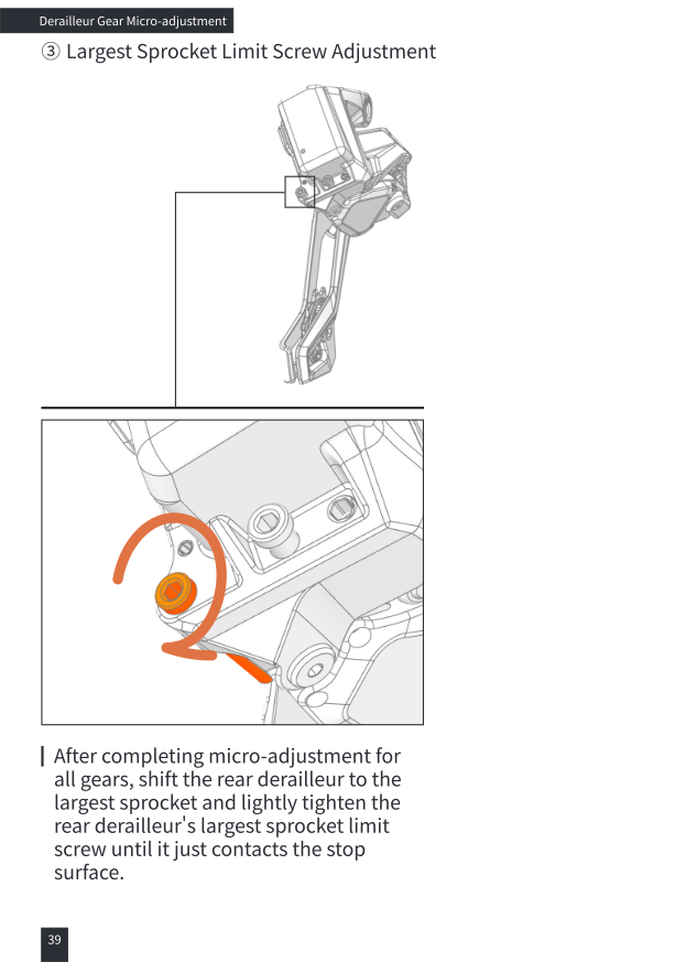
After completing micro-adjustment for all gears, shift the rear derailleur to the largest sprocket and lightly tighten the rear derailleur's largest sprocket limit screw until it just contacts the stop surface.
APP Special Features
Dual-Control Shifter Button Customization
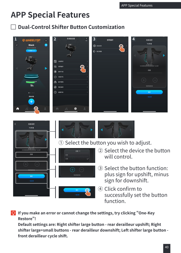
- Select the button you wish to adjust.
- Select the device the button will control.
- Select the button function: plus sign for upshift, minus sign for downshift.
- Click confirm to successfully set the button function.
If you make an error or cannot change the settings, try clicking "One-Key Restore"! Default settings: right shifter large button = rear derailleur upshift; right shifter large+small buttons = rear derailleur downshift; left shifter large button = front derailleur cycle shift.
Gear Mirroring
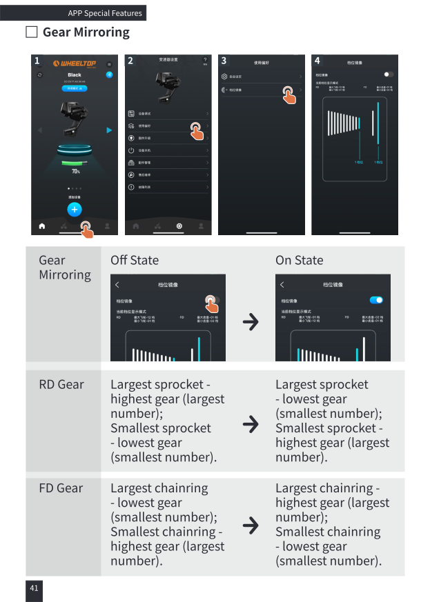
Off state: largest sprocket = highest gear number, smallest sprocket = lowest gear number; largest chainring = lowest gear number, smallest chainring = highest gear number.
On state: largest sprocket = lowest gear number, smallest sprocket = highest gear number; largest chainring = highest gear number, smallest chainring = lowest gear number.
Indicator Light Overview
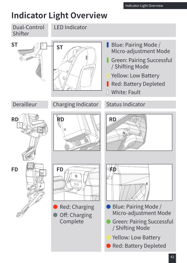
Dual-Control Shifter LED: Blue = pairing/micro-adjustment mode; Green = pairing successful/shifting mode; Yellow = low battery; Red = battery depleted; White = fault.
Derailleur charging indicator: Red = charging; Off = charging complete.
Derailleur status indicator: Blue = pairing/micro-adjustment mode; Green = pairing successful/shifting mode; Yellow = low battery; Red = battery depleted.
Maintenance
Component Replacement
If the rear derailleur, front derailleur, or dual-control shifter is individually damaged, refer to "System Pairing & Derailleur System Installation" for replacement. When replacing a dual-control shifter or front derailleur, only the replaced component needs to be re-paired with the rear derailleur. When replacing the rear derailleur, all components need to be re-paired.
- Only use CR2032 batteries for shifters/dual-control shifters.
- It is recommended to clean the derailleurs regularly.
- The operating temperature for the derailleur is −10°C to 50°C.
- The batteries for the rear and front derailleurs are integrated designs. Do not disassemble them unless you are a professional. For air transport requiring disassembly, seek professional assistance.
Maintenance Cycle Suggestions
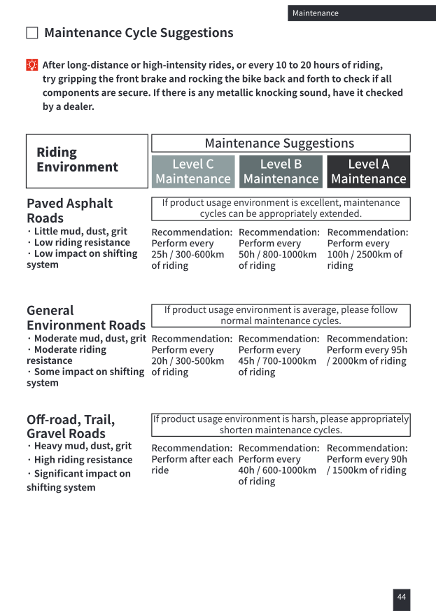
After long-distance or high-intensity rides, or every 10 to 20 hours of riding, grip the front brake and rock the bike back and forth to check if all components are secure. Any metallic knocking sound should be checked by a dealer.
- Paved asphalt roads (little mud/dust, low impact): Level C every 25h/300–600km, Level B every 50h/800–1000km, Level A every 100h/2500km.
- General environment roads (moderate mud/dust): Level C every 20h/300–500km, Level B every 45h/700–1000km, Level A every 95h/2000km.
- Off-road, trail, gravel roads (heavy mud/dust): Level C after every ride, Level B every 40h/600–1000km, Level A every 90h/1500km.
In excellent conditions, cycles can be extended; in harsh conditions, shorten them.
After-Sales & Contact
Lanxi Wheel Top Cycle Industries Co., Ltd.
TEL: +86(579) 83881076 / 83888356
Scan the After-Sales Service, Customer Service, or Contact Us QR codes in the original manual to reach WHEELTOP directly, or use the download link in the sidebar for the full illustrated PDF.
Need Help?
For anything not covered here — pairing errors, calibration issues, or a suspected fault — contact us and we'll walk you through it. As an authorized WHEELTOP partner, we provide hands-on installation and tuning support for every EDS TX order.